Assignment 2: 2D Cubies Illusion
Due: Friday, Feb 7, 2025
Important
Download the template Grasshopper document here: A2 Boilerplate.
Note
This assignment comes with a lot of boilerplate. There’s a lot here that you aren’t expected to be able to recreate, but if you’re interested, of course do poke around.
Context
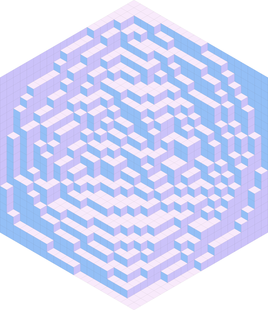
For this assignment, we’ll be creating the illusion of having 3D cubes on a 2D plane.
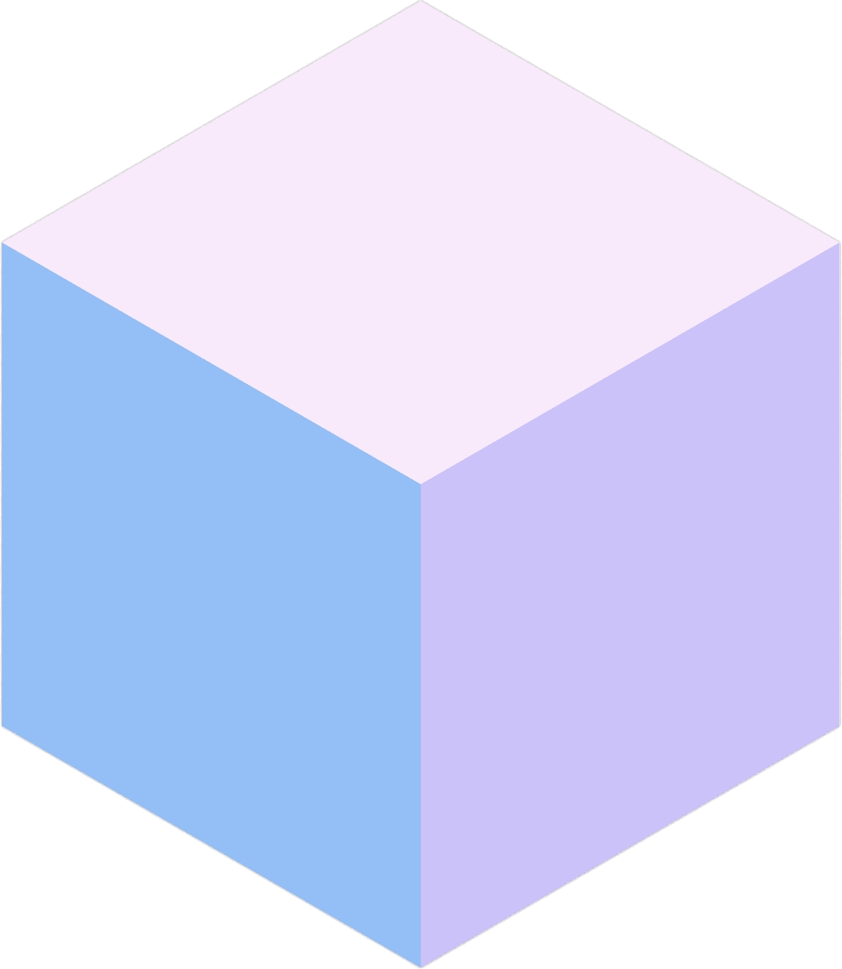
In general, you can tile a hexagon with 3 types of rhombi. When colored uniquely, these rhombi can give the appearance of filling a 3-dimensional box with little cubes. In this assignment, these perceived cubes will be called “cubies.” A cubie is made of 3 rhombi.
Each of the three faces can be labeled with 2D cardinal directions indicating the way it is facing: North, Southeast, and Southwest.
An “inverted” cubie can be created by rotating the three rhombi around their common vertex. On its own, this gives the impression of an upside-down cubie, but in context with others, it can give the impression of negative space where a cubie isn’t.
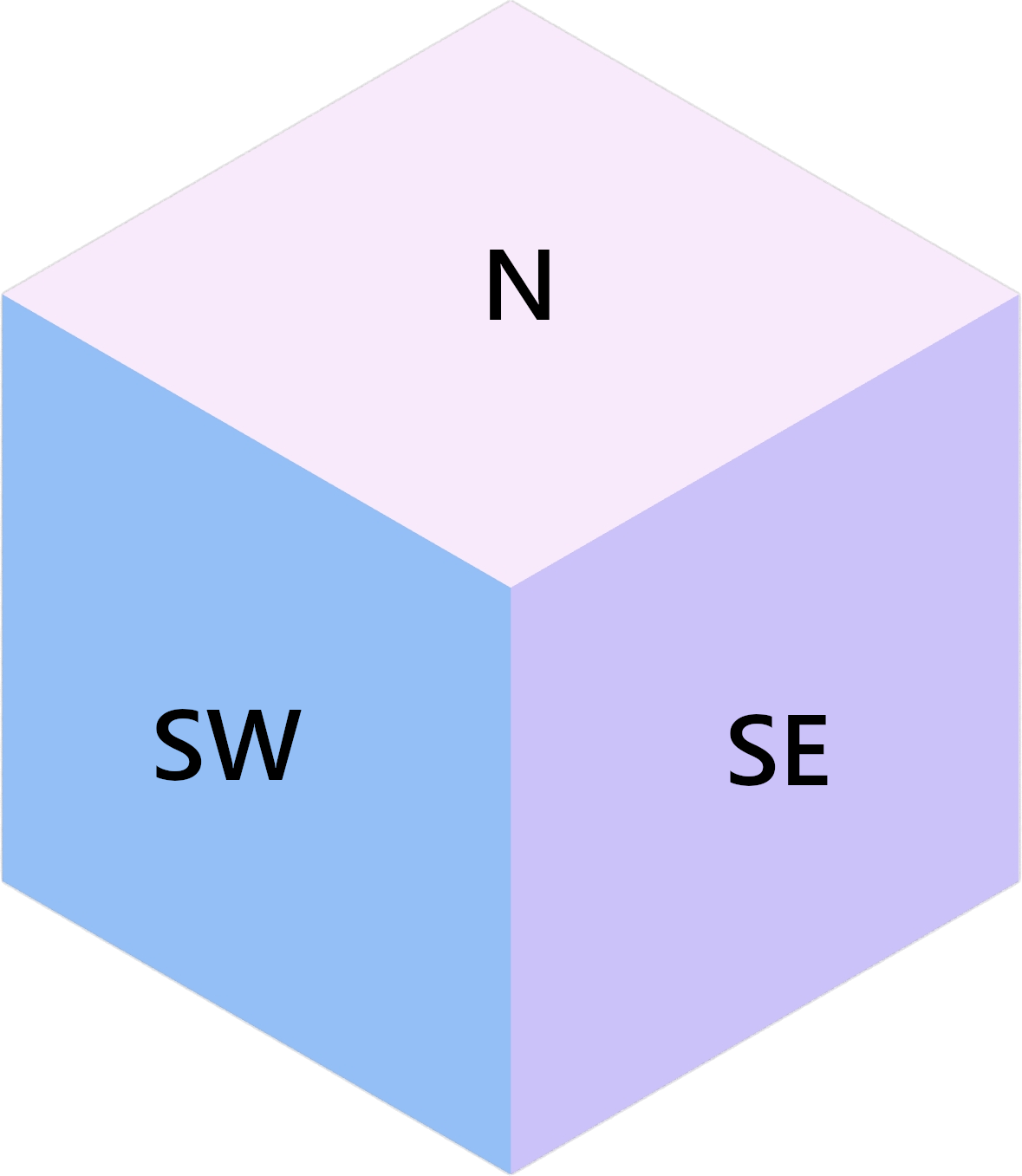
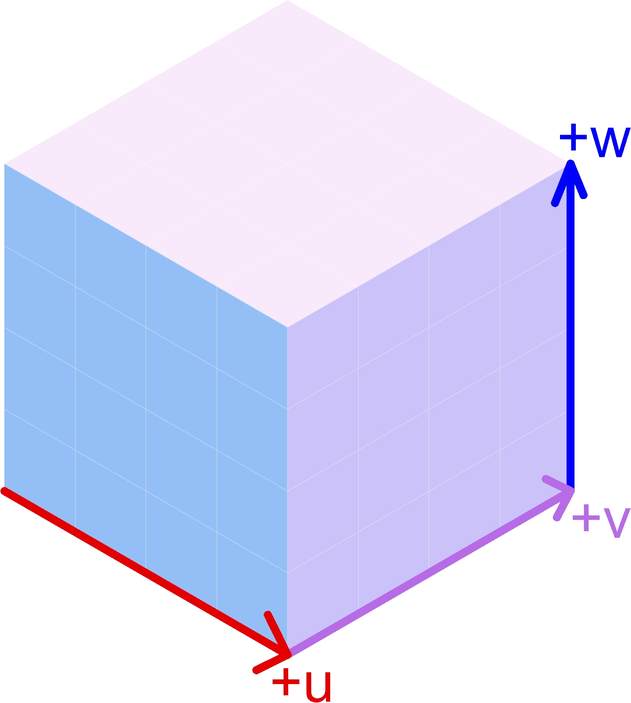
A cubie with face directions labeled.
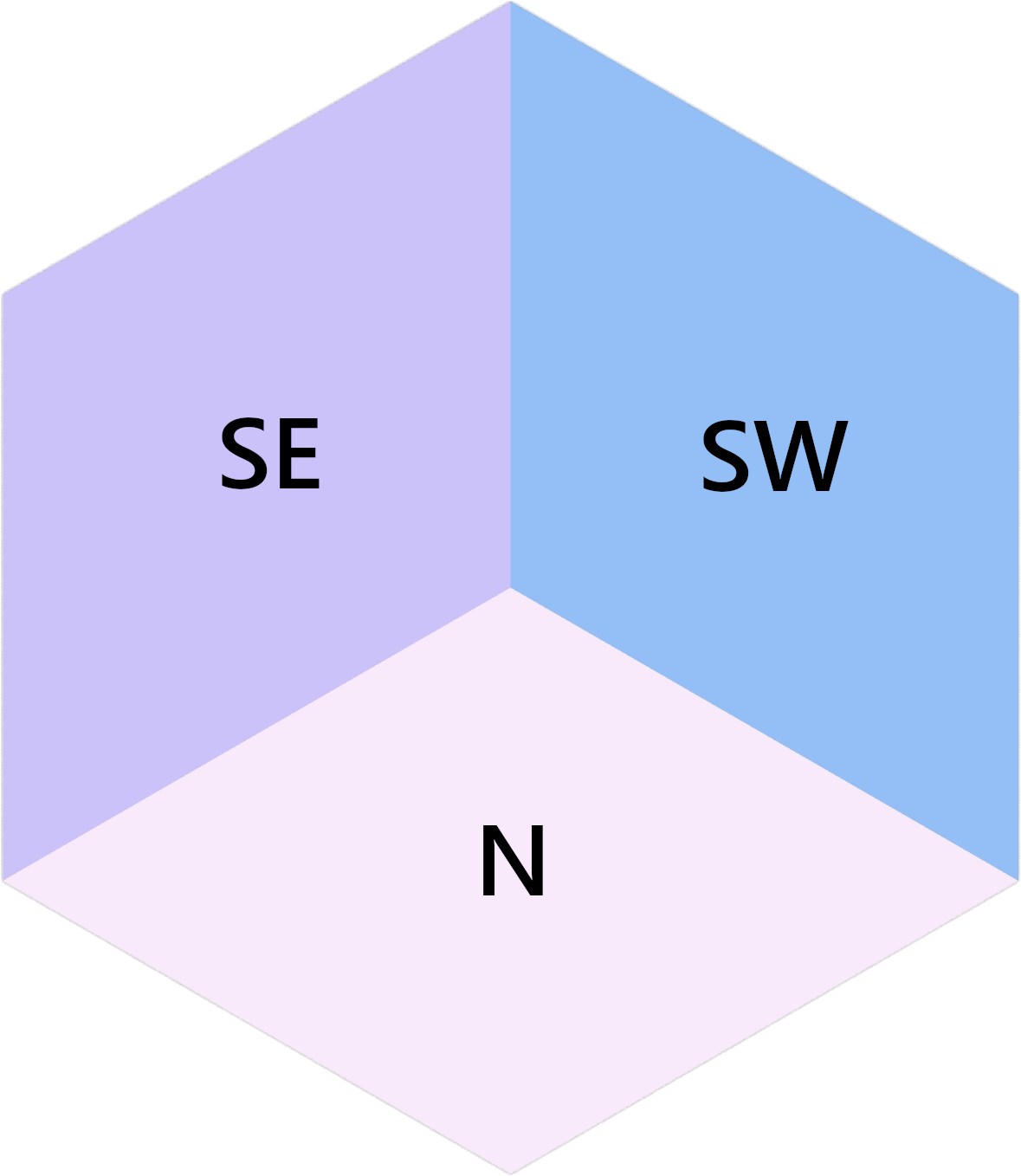
An inverted cubie with face directions labeled.
In a real 3D space, cubies can be indexed with 3 coordinates: u, v, and w.
In 2D hexagon space, increasing u looks like moving Southeast (down and right),
increasing v looks like moving Northeast (up and right), and increasing w looks
like moving North (up). This isn’t the only way to structure the coordinate system, but
it’s the way it’s been done here.
Because the hexagon is a 2D “projection” of the 3D space, you have been provided with
a function to convert coordinates (u, v, w) into coordinates on the plane:
- get_point(u: int, v: int, w: int) Vector3d
Returns the projected cubie corner at coordinates
(u, v, w). Although the returned type is a 3D vector, it’s Z component will be 0.- Parameters:
u – The u coordinate of the cubie corner
v – The v coordinate of the cubie corner
w – The w coordinate of the cubie corner
- Returns:
A Rhino.Geometry.Vector3d with the coordinates of the cubie corner projected onto the XY plane (Z = 0)
Important
Because the hexagon is a projection of 3D space, multiple coordinates (u, v, w)
can map to the same point in the hexagon. This is a useful fact to know.
Cubies can be stacked together. One thing that will always be true of such stacks is that a stack of cubies will never be taller than either the stack Northeast or Northwest of it (symmetrically, a cubie stack will never be shorter than either the stack Southeast or Southwest of it). This condition gives the tiled hexagon the appearance of containing cubie stacks.
Configuration
You have some options for configuring the output. In a group are a bunch of parameters that affect the generation:
Parameters Group
Extent U: how many cubies extend in the positive
udirection.Extent V: how many cubies extend in the positive
vdirection.Extent W: how many cubies extend in the positive
wdirection.Seed: a seed to use for the random generation of the cubie stack heights. This will allow you to recreate results consistently.
Preparation Strategy: After randomly generating a set of heights to use for cubie stacks, you have some options for how to arrange these heights in a valid configuration
Random Bubble Sort: Cubie stack heights are distributed as randomly as possible. This trends towards an “Arctic Circle” (see this YouTube video if you like math and want to learn more).
Sort along U then along V: Heights are sorted along the
udirection, then along thevdirection. This trends towards an up-left slope.Sort along V then along U: Heights are sorted along the
vdirection, then along theudirection. This trends towards an up-right slope.All 0: Overrides all heights to be 0.
All Max Height: Overrides all heights to be the maximum of the randomly generated heights. In general, this will be Extent W, but it could be shorter.
Rendering Options Group
If you’d like, you can change the colors used to create the materials used for the 3 different groups of faces. I chose the default colors by looking for a nice 3-color palette on coolors.co.
You can also change the origin point of the hexagon (the Southwest corner).
Task Description
In the template Grasshopper file above, you will edit the Python 3 script node titled “Generate Faces”. The node itself will be red, and it’s contained in a group with the caption “Edit Me!”
Inputs
The script node accepts 4 parameters:
- w_heights: list[list[int]]
w_heights[extent_u - u][v + 1]is the height of the cubie stack with a western corner at(u, v).
When you’re implementing your code (see Things to Implement), you’ll
be provided with u, v, and
Explanation of w_heights
You do not need to be familiar with the structure of w_heights, but if you’re
curious, you can expand the dropdown and see. Being familiar with this structure is
important if you’d like to customize your own w_heights input tree for testing
or making cool pictures, or if you’d like to print out w_heights for debugging.
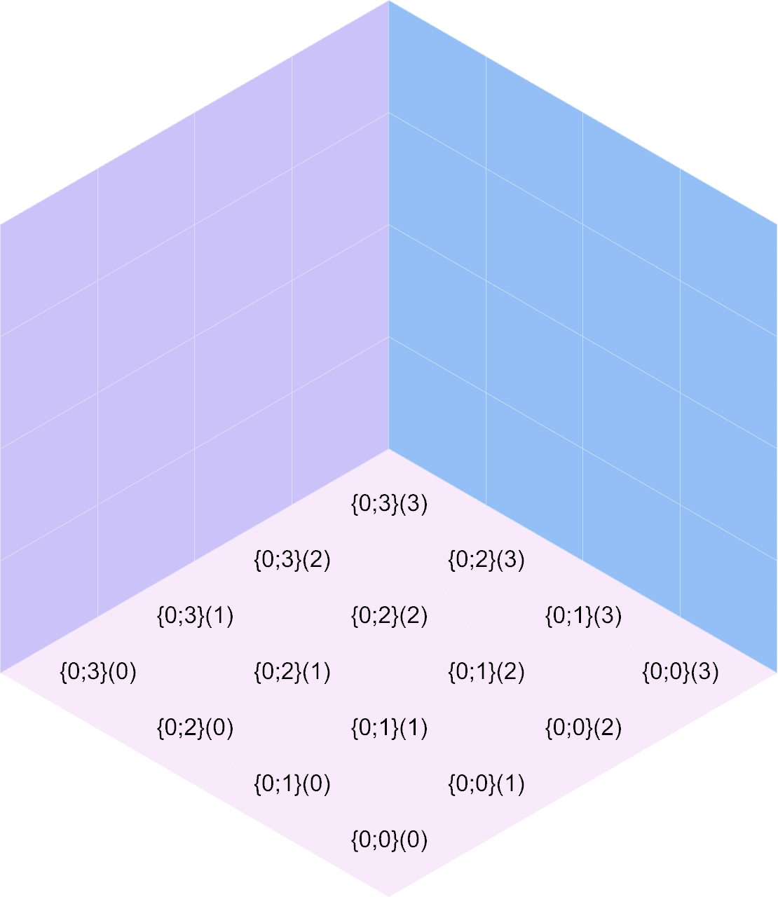
Specifics for w_heights
The input accepted by w_heights is slightly different from the structure of the
3D space imagined in the hexagon. Path {0;0}(0) is the height of the cubie stack
in the Southernmost part of the grid. As u increases in {0;u}(v), the actual
u coordinate of the stack decreases. This isn’t important for you to mess with,
but if you’d like to create your own w_heights instead of using one of the randomly
provided trees from within the Grasshopper document (whether for testing or for getting
a good picture), you’ll need to know this. The idea is that the “closest stack to the
camera” will be the first path in the tree.
With the provided options for w_heights, this ensures that for any u and v,
the height at {0;u}(v) will be at most the smaller of the heights at {0;u + 1}(v)
and {0;u}(v + 1).
Once passed to the Python 3 script node, it gets converted to a list of lists where
w_heights[0][0] corresponds to the path {0;0}(0). An additional 0 is placed
at the beginning of each row, and an additional row is added so that w_heights[1][1]
corresponds to the path {0;0}(0). For a given (u, v), the western corner
of a stack, that stack’s height will be at w_heights[extent_u - u][v + 1]. The
height of the stack to the Southeast will be at w_heights[extent_u - u - 1][v + 1],
and the height of the stack to the Southwest will be at w_heights[extent_u - u][v].
For stacks on the Southern border, these two extra heights will be 0.
If you’d like to print out the contents of w_heights for testing, you can do so by
placing the following code above the double for loop in the “Things to Implement”
section of the code:
print("\n".join(str(row) for row in w_heights))
If you do this, you’ll want to be familiar with the structure of w_heights (see
the dropdown above).
Outputs
You’ll need to populate 3 output lists with surfaces corresponding to the faces
of the cubies that can be seen, given w_heights:
- north_faces: list[Rhino.Geometry.Surface]
A list of North-facing faces, created with rs.AddSrfPt.
- southeast_faces: list[Rhino.Geometry.Surface]
A list of Southeast-facing faces, created with rs.AddSrfPt.
- southwest_faces: list[Rhino.Geometry.Surface]
A list of Southwest-facing faces, created with rs.AddSrfPt.
These will be populated with the add_xxx_face functions that you’ll be implementing.
Things to Implement
Inside the script, scroll down to the “Things to Implement” section. Here, you’ll see 3 functions to implement:
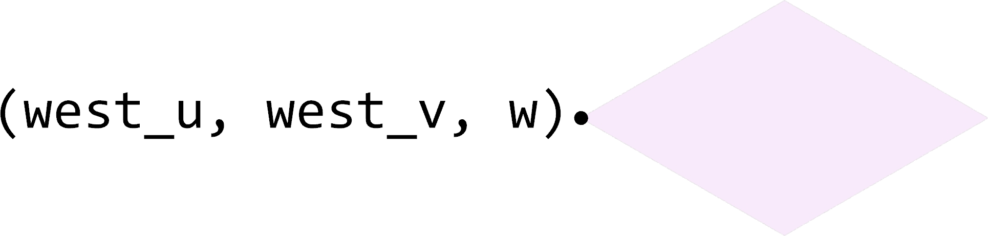
- add_north_face(west_u: int, west_v: int, w: int) None
Add a north-facing surface to the “north_faces” list.
- Parameters:
west_u – The u coordinate of the western corner of the face
west_v – The v coordinate of the western corner of the face
w – The w coordinate of the face
- add_southeast_face(u: int, southwest_v: int, southwest_w: int) None
Add a southeast-facing surface to the “southeast_faces” list.
- Parameters:
u – The u coordinate of the face
southwest_v – The v coordinate of the southwestern corner of the face
southwest_w – The w coordinate of the southwestern corner of the face
- add_southwest_face(southwest_u: int, v: int, southwest_w: int) None
Add a southwest-facing surface to the “southwest_faces” list.
- Parameters:
southwest_u – The u coordinate of the southwestern corner of the face
v – The v coordinate of the face
southwest_w – The w coordinate of the southwestern corner of the face
Note
You’ll want to use get_point() to identify the 4 corner points of each
face your create. The input to the function is the (u, v, w) coordinates of one
corner, and you’ll need to figure out which (u, v, w) coordinates correspond to
the other 3 corners of the face.
The Nested Loop
Finally, you’ll also need to implement the contents of a double for loop that will
use these 3 functions. Inside the nested for loop, you’ll see 3
raise NotImplementedError. For each one, you’ll need to use the functions you implemented
to add some faces to the output lists. When doing this, you’ll be provided with:
- u
The
ucoordinate of the westernmost corner of the current cubie stack.
- v
The
vcoordinate of the westernmost corner of the current cubie stack.
- w
The height of the current cubie stack.
- w_southeast
The height of the cubie stack to the Southeast of the current cubie stack. If the current cubie stack is on the Southeastern edge of the hexagon (
u = extent_u), this will be 0.
- w_southwest
The height of the cubie stack to the Southeast of the current cubie stack. If the current cubie stack is on the Southwestern edge of the hexagon (
v = 0), this will be 0.
To completely tile the hexagon, there are East and West “walls” that need to be filled
if there is no cubie stack in front of it. Inside the nested for loop, there are
two if statements that set up this condition, which need to contain your implementation
to fill the walls.
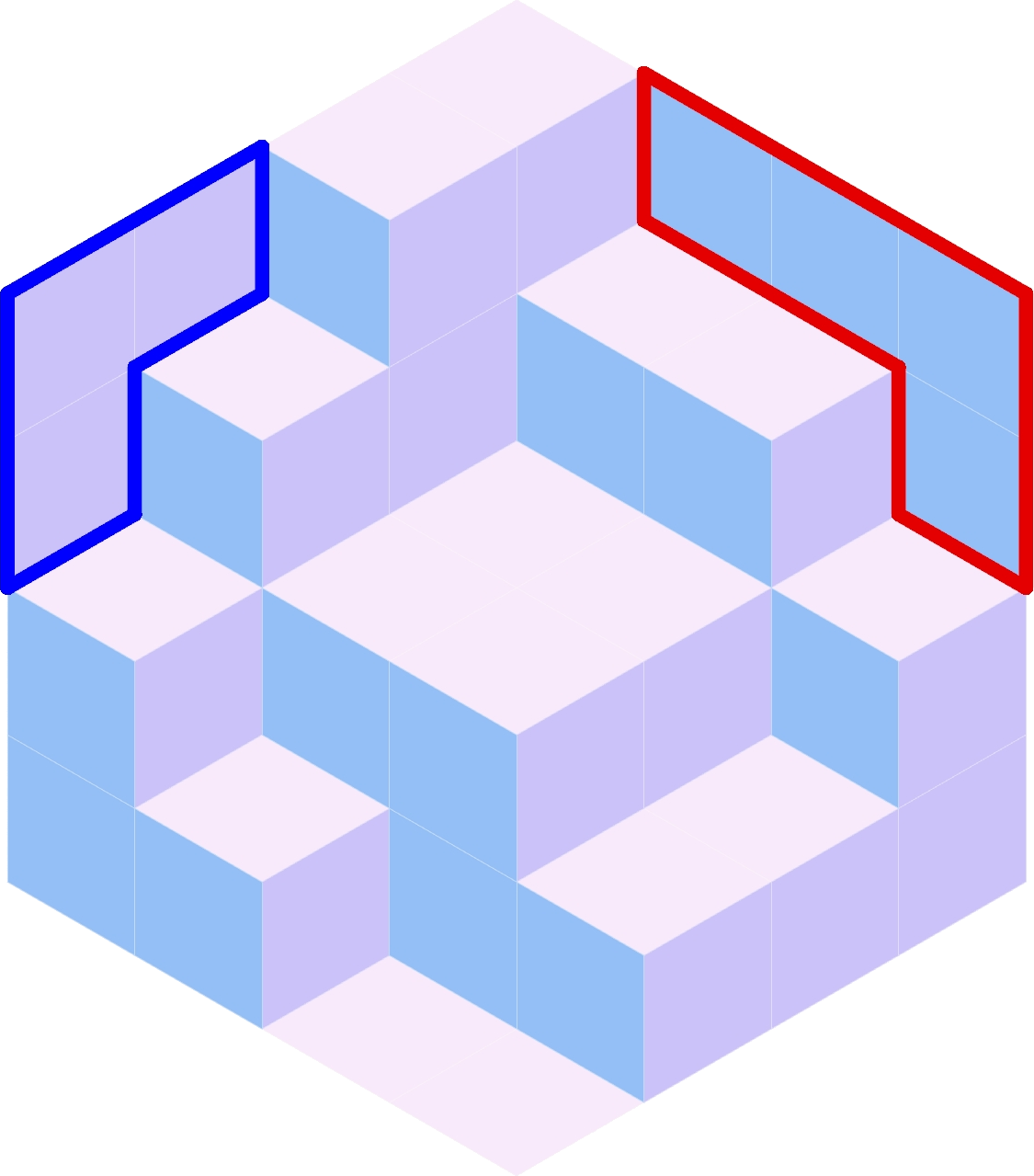
Example configuration with the East wall outlined in red and the West wall outlined in blue.
Example
This is an example of the inputs provided to the “Generate Faces” Python 3 script node and the expected output.
Inputs
extent_u = 4extent_v = 4extent_w = 4w_heightsis a tree containing the following information:{0;0}¶00 11 21 32
{0;1}¶00 12 22 33
{0;2}¶01 12 22 33
{0;3}¶02 13 24 34
After processing,
w_heightswill be a list containing the following information:[0, 0, 0, 0, 0] [0, 0, 1, 1, 2] [0, 0, 2, 2, 3] [0, 1, 2, 2, 3] [0, 2, 3, 4, 4]
This was generated with the “Seed” parameter set to 524 and the “Preparation Strategy” set to “Random Bubble Sort”.
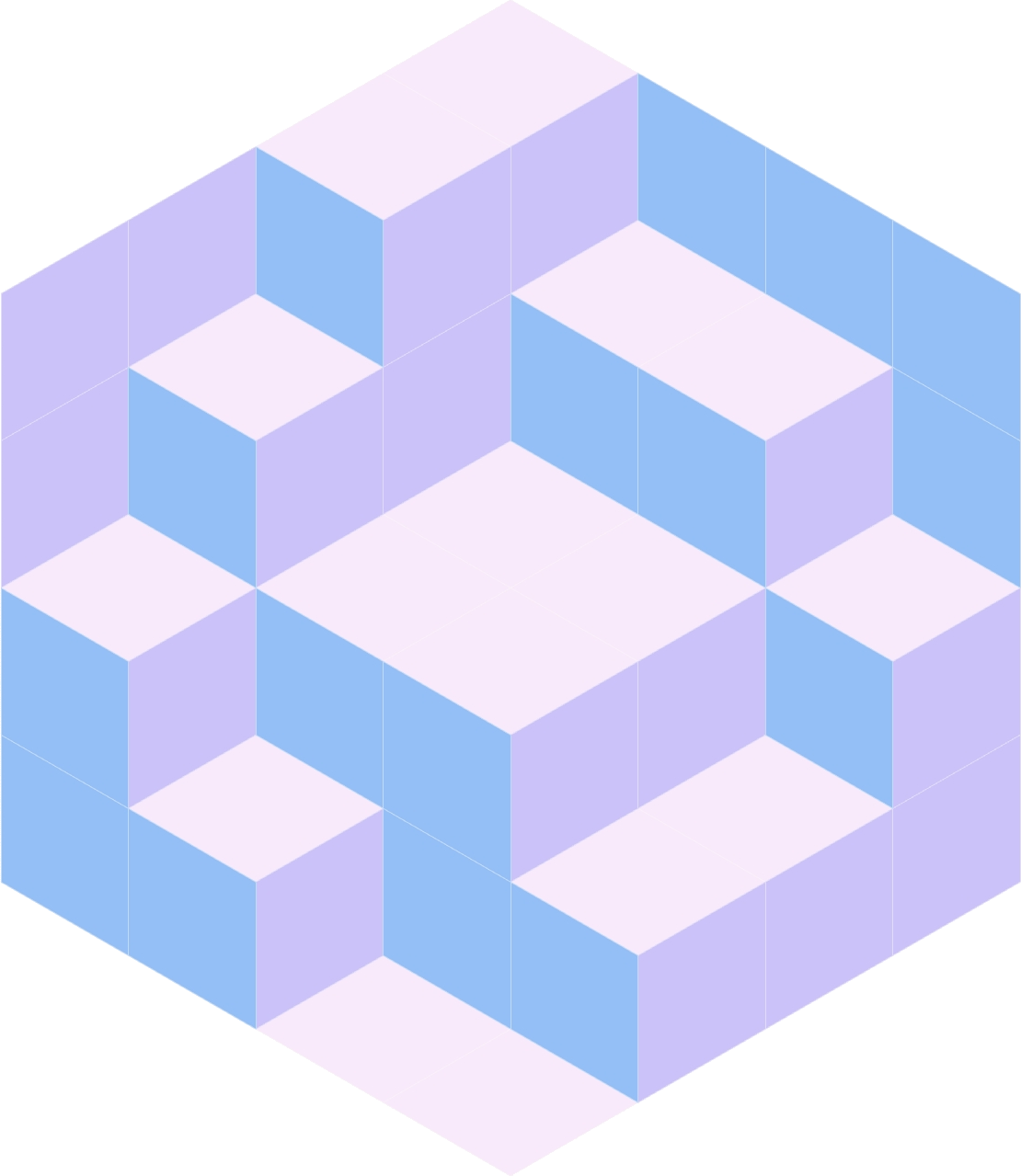
Outputs
The output lists each contain 16 surfaces, and the final output looks like:
Tips
You’ll want to use rs.AddSrfPt to create the surfaces used to represent the cubie faces.
If you want to know how many faces you’ll need to output, you’ll need
extent_u * extent_vNorth faces,extent_v * extent_wSoutheast faces, andextent_u * extent_vSouthwest faces.If you want to create your own input to
w_heights, refer to the Dropdown above.If you want to preview the points of the hexagon, you can create a new output node on the Python 3 script node you’re editing called “test”, set the Type Hint to Point3d, and paste the following code at the bottom of your Python script. Comment out any
raise NotImplementedErroras needed.test = [] for u in range(extent_u + 1): for v in range(extent_v + 1): for w in range(extent_w + 1): test.append(rs.AddPoint(get_point(u, v, w)))
Once you have this, make a Move node, connect the
testoutput into the Geometry input, and connect the Origin point from the “Rendering Options” group to the Motion input.I recommend starting by creating the North faces before trying to the Southeast and Southwest faces. This will help you make sure that you’re getting the apparent heights correct.
Clarifications
Inside the double-nested for loop (see above), you’ll have
access to 5 variables: u, v, w, w_southeast, and w_southwest.
The coordinates (u, v, w) correspond to a point in 3D space. This point is projected
into 2D space with the get_point function.
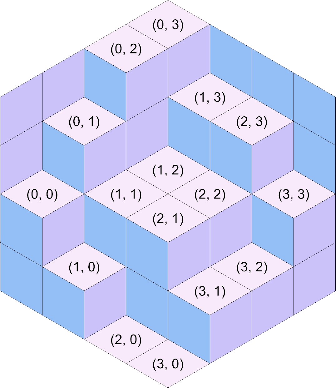
u and v correspond to the stack you’re adding faces for. In the figures below,
each stack is shown with their corresponding (u, v) coordinates.
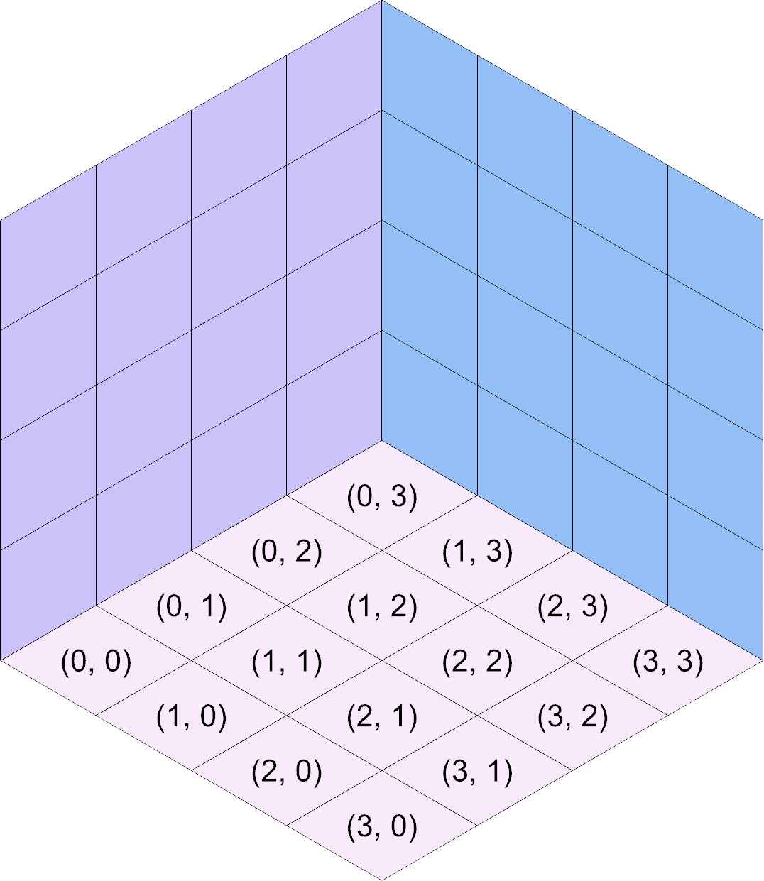
When you’re in the loop, (u, v, 0) corresponds to the western point of the bottom of
the stack. Similarly, (u, v, w) corresponds to the western point of the north face
of the entire stack. As such, t’s recommended that you pass the u, the v, and the
w that you have access to from within the loop into add_north_face (i.e., run
add_north_face(u, v, w) verbatim).
When implementing the add_north_face function, you pass in the (u, v, w) coordinates
of the southwest corner, provided in variables as west_u, west_v, and w respectively.
You can get the 2D point corresponding to that corner with get_point(west_u, west_v, w).
For the other 3 corners of the face, w will stay the same, but you’ll need to add
1 to west_u, west_v, or both when calling get_point to get the 2D points
corresponding to those corners. This will look incredibly similar to creating the closed
polylines for the parallelogram grid created in Week 5. Open the source code dropdown
and look down to the double-nested for loop under the comment “Generate cells” to see
how u and v were modified in that situation. Of course, this is slightly different
because you’ll be using get_point with 3D coordinates instead of accessing a list of
lists. You also won’t need to repeat the first corner when calling rs.AddSrfPt.
Once you have the 4 corners, you’ll need to provide them to rs.AddSrfPt as a list:
surface = rs.AddSrfPt([corner1, corner2, corner3, corner4])
In the code block above, I use a list literal to create the list passed to rs.AddSrfPt. Alternatively, you could create an empty list and append them each.
Important
The corners provided to rs.AddSrfPt MUST each be the output of get_point.
u, v, and w (and any modified names like west_u) are 3D coordinates
that need to be converted to the corresponding 2D coordinates with get_point.
Southeast and Southwest Faces
Creation of the Southeast and Southwest faces is facilitated by the two variables w_southeast
and w_southwest, respectively. In the figures above, take
a look at the stack labeled (2, 1). The height of the stack is 2 (w = 2), the
height of the stack to the Southeast at (3, 1) is 1 (w_southeast = 1), and the
height of the stack to the Southwest at (2, 0) is 0 (w_southwest = 0).
The difference in heights to the Southeast means 1 Southeast face will need to be added with
add_southeast_face. I encourage you to provide the Southwest corner (u, v, w)
coordinates of these faces to add_southeast_face. For Southeast faces, u will
always be the same, but v and w will need to vary in order to find the other 3
corners. I suggest providing the Southwest instead of the Northwest corner of the face
so that you can create 1 face for each w_step ranging from w_southeast to w
(not including w).
Important!!!
That last sentence is a big hint, suggesting how you might want to create a for
loop using range.
Similarly, the difference in heights to the Southwest means 2 Southwest faces will need
to be added with add_southwest_face, 1 for each w_step ranging from w_southwest
to w (not including w). For Southwest faces, v is constant, while u and
w need to vary to find the other 3 corners.
Additionally, if the stack you’re working on is against the wall and w is not w_extent,
you’ll need to add faces for each w_step ranging from w to w_extent (not including
w_extent) on the wall.
(u, v, w) for Southeast and Southwest Faces
When adding Southeast and Southwest with add_southeast_face or add_southwest
face, you’ll sometimes need to add 1 to either the u or v provided to you
in the nested loop when calling the functions. Remember that you want to provide
the functions with the (u, v, w) coordinates of the Southwest corner of the face.
Increasing u by 1 shifts the corresponding 2D point (computed with get_point)
down and right. Increasing v by 1 shifts the corresponding 2D point up and right.
Take some time to figure out when you’ll need to add 1 to u and when to add 1
to v. Or you can just try out different things and see what works.
Submission
Deliverables
When submitting your assignment, upload a .gh file containing your solution. Also
create a handful (minimum 5) of pictures showcasing the rigorousness of your solution.
This means you should play with different extents, seeds, and preparation strategies.
Feel free to also play with the colors used for each face type or create your own inputs
to w_heights.
If you haven’t made renderings from Grasshopper, I’d suggest right-clicking the Custom Preview node, selecting Bake, changing your viewport to use the Rendered model view, and print out the surfaces you create to a picture.
Rubric
Points |
Requirements |
|---|---|
15 |
Your solution correctly makes a “filled” hexagon when the preparation strategy is set to “All Max Height”. |
15 |
Your solution correctly makes an “empty” hexagon when the preparation strategy is set to “All 0”. |
15 |
Your solution does not create any overlapping surfaces. |
15 |
Your solution creates a completely tiled hexagon, with dimensions matching the Extent parameters. |
40 |
You have created at least 5 pictures showcasing the rigorousness of your solution. |